How to build a Trojan Phazer light gun from an Amstrad Magnum
Introduction
If we take a Trojan Phazer, a Sinclair light gun and an Amstrad Magnum and we compare them, we can conclude that they are almost identical -at least externally. They share the same kind of outer case, and it is also true for the board inside the Trojan Phazer and the Amstrad Magnum. On these boards, I suppose the solder point marked 'P1' or 'P' is ground, 'P2' is the signal coming from the sensor, and 'P4' is 5v.
To build this project you will need:
1. Mounting the RJ-11 connector
If you have bought a standard flat cable, the order of the wires inside it will be the following: white, black, red, green, yellow and blue. Incidentally, the blue wire may be grey, and the red one may be pink.
According to this web page, http://www.wikilearning.com/posicion_del_conector-wkccp-5424-3.htm, the link between the wires and the pins inside the RJ-11 connector is the following:
|
Pin at RJ-11 conn. |
Colour of the wire |
|
1 |
Blue/Grey |
|
2 |
Yellow |
|
3 |
Green |
|
4 |
Red/Pink |
|
5 |
Black |
|
6 |
White |
Once you have crimped the cable, you may tin the wires at the other edge. Take into account that you won't need the black one, since it is FIRE2 signal -which is not present in the Trojan Phazer.
2. Openning the Magnum gun
The two pieces of the Magnum case are glued, as different to the Trojan ones. Opening the Magnum without harming the case is extremely difficult.
Special care must be taken with the gun barrel of the device, since it can be easily broken. You should also take care in not losing the lens of the gun.
3. Soldering, and finishing the job
Once you have opened the Magnum case, the first thing is desoldering the wires inside it. You will find two wires attached to the switch of the trigger, three more attached to the board, and one linking the switch to the board. Take all of them out.
Now you have to solder the new cable (the one you have crimped) in this way:
|
Pin at RJ-11 conn. |
Colour of the wire |
Solder point |
|
1 |
Blue/Grey |
P/P1 on the board |
|
2 |
Yellow |
Pin 1 (or common pin) at the switch |
|
3 |
Green |
P2 on the board |
|
4 |
Red/Pink |
Pin 4 at the switch (this is the pin that closes the circuit) |
|
6 |
White |
P4 on the board |
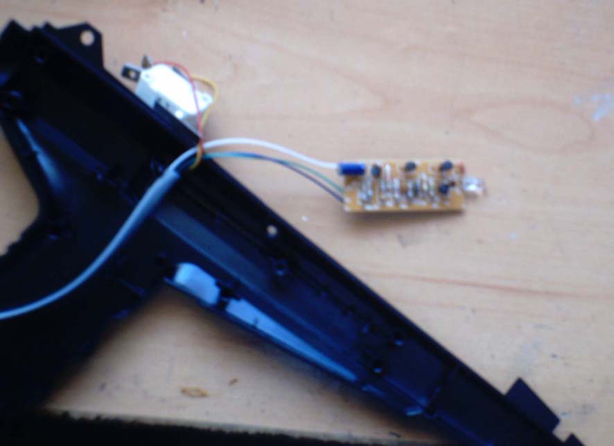
This is a pic of the project finished:
Hints:
Thanks to cpcmaníaco for providing a Trojan Phazer and allowing me to open it, and for encouraging me to write this article.
Very special thanks to Supernena Cactus and MiguelSky for supervising this english translation.
Author: j.f.
eMail:
deepfb2002@yahoo.es